Analysis
Analysis Summary
Analysis of dynamics, statics, mechanical design, and strengths of utilized materials was done to determine the shear and normal stresses acting on the chassis and suspension components. Below are the analyses to determine various design factors such as optimal materials, necessary dimensions of parts and components, and understanding the predicted outcomes of forces acting on the chassis and suspension during required testing.
Design Requirements
-
RC Baja Truck must withstand a vertical 1.5 foot drop without any breakage or bottoming
-
Must withstand a front impact at 15 mph
-
Truck must weigh no more than 10 lbs.
-
deflect no more than 0.25 inches under 40lb load
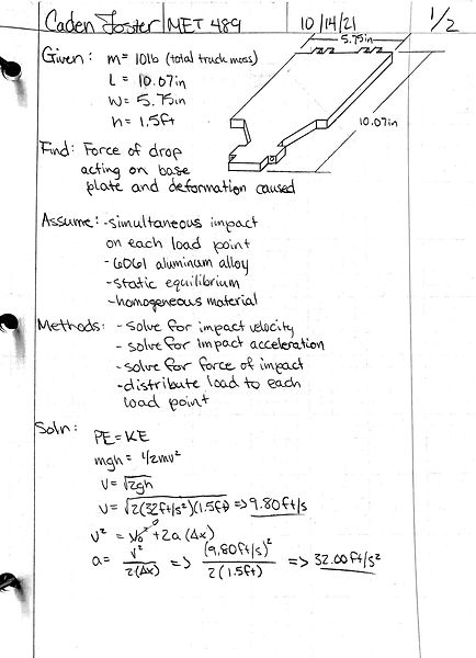
ii. Analysis 2 Drop Test
Figure A.2 depicts the impact velocity and acceleration at 9.80ft/s and 32.00ft/s2 respectively. This causes an overall force of 44.42N of force acting at the center of the body continued in Figure A.3. This will yield approximately 11.06N of force acting on each load location on the chassis base plate. Assuming the base plate being a rough rectangle, the moment of inertia from the center of the plate will cause a deflection of approximately 0.0718in.
i. Analysis 1 Thickness of Baseplate
Figure A.1 depicts the analysis of the force of a 1.5 drop assuming 10lbs truck weight. It will solve for the necessary diameter and absorption forces required to withstand the drop without buckling/failing.


iii. Analysis 3 Critical Load Before Buckling
Figure A.3 depicts the analysis of how much force is required to cause the baseplate of the chassis to buckle. With the chassis assumed to be pinned at each end, the effective length using a k factor of .7 was applied. Solving for the critical load, a force of 14kN would cause the baseplate to buckle, and therefore will be well outside the realm of possibility for this project.

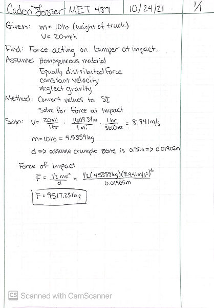
iv. Analysis 4 Impact Test
Figure A.4 depicts the analysis of the force of impact assuming 10mph at the point of impact and the material constraints required to not have destructive forces on the chassis.
vi. Analysis 6 Minimum Screw Diameter
Figure A.6 calculates the the smallest diameter of screws possible in order to maintain structural integrity and light weight. The smallest diameter depicted below states no less than .114 in, therefore the smallest standardized screw diameter would be .125 or 1/8 in in diameter.
v. Analysis 5 Thickness of Front Bumper
Figure A.5 shows the calculations that define the minimum thickness of the bumper in order to withstand a 10mph impact.


viii. Analysis 8 Stiffness of Shocks
Figure A.8 depicts the analysis of the force of a 1.5 drop assuming 10lbs truck weight. It will solve for the necessary diameter and absorption forces required to withstand the drop without buckling/failing.

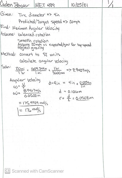
vii. Analysis 7 Maximum Angular Velocity
Figure A.7 shows the maximum velocity that the wheels will undergo at the anticipated max speed of the vehicle. With an expected max velocity of 20 mph, the calculated angular velocity was 176 rad/s.
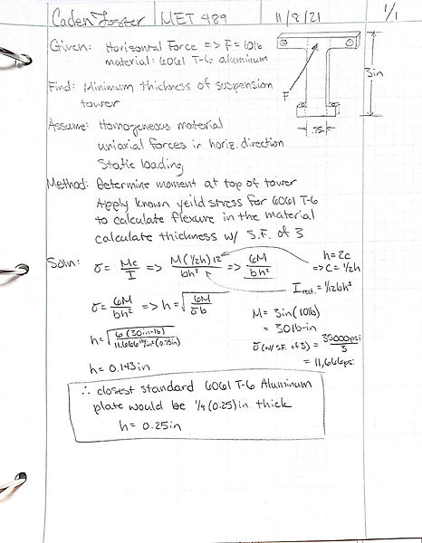
ix. Analysis 9 Minimum Thickness of Front Shock Tower
Figure A.9 depicts the analysis of the force of 10lbs due to the weight of the truck weight acting on the Front Shock Tower. It will solve for the necessary thickness required so that the tower doesn't buckle and bend due to the forces acting at the connection locations for the shocks.