
Testing
Testing Summary
The constructed RC truck was designed to function as any RC vehicle would as well as being able to undergo and pass a multitude of tests. The testing portion of the ASME RC Baja Project includes the Drop Test, Front Impact Test, Chassis Deflection Test, and the basic performance testing during the Baja event. This will include the Slalom, Straight, and the outdoor Baja event. Other than the performance testing, the testing requirements will be on a pass vs. fail basis in determining the RC's effectiveness.
The Drop Test included dropping the R/C from 1.5 feet and measuring the difference in the position of the chassis from its resting height to the new height after each drop. The Impact Test incorporated driving the R/C into a concrete wall at the speeds 5, 10, and 15mph to test the bumper effectiveness. The final test, Chassis Deflection, loaded multiple weights on the suspended chassis plate and determined the deflection of the plate relative to the ground after each applied weight block.
One testing issue that occurred during the Impact Test was the purchase of a defective battery that was later discovered to have a completely depleted cell. After using the battery to the point of a low charge where the battery no longer provided enough power to drive the motor, recharging of the battery was attempted until realizing the battery was defective and deemed unsalvageable. A new battery was purchased and the final 15mph speed trial of the Impact Test was conducted successfully.
Drop Test Video
The video above depicts the R/C being dropped from 1.5 feet with a measuring tool in the background to give a visual reference of the total travel of the suspension with respect to the chassis plate relative to the ground. The resting position relative to the ground of the front and rear corners of the chassis were measured prior to the drop. The final resting position of the front and rear corners of the chassis were measured after the drop and compared.

Fig. 1: Drop Test Data
Figure 1 depicts the resting position of the chassis relative to the ground before and after the 1.5 foot drop. The difference in these resting positions are also marked in the deflection column to give a relative understanding of how effective the shock were in bringing the chassis back to its normal resting position.

Fig. 2: Chassis Bottoming
It can been seen in Figure 2 that the springs were not strong enough to withstand the force of impact to prevent the chassis from bottoming out. This is due to the springs not having a high enough K value to support the weight of the chassis and its components and dampen the drop from 1.5 feet.

Impact Test (5mph)

Impact Test (10mph)
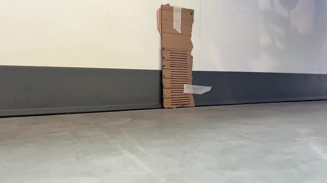
The Impact Test videos above illustrate impact of the R/C at 5 and 10mph respectively and how they impacted the bumper upon collision. The R/C was lined up ten feet from the wall to allow time to reach the required speed to collide with the wall. The bumper and other R/C components were inspected for any damage or breakage.
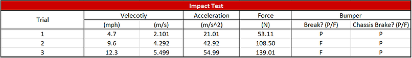
Fig. 3: Impact Test Data
Figure 2 describes the velocity of the R/C at impact in both (mph) and (m/s) for relative terms as well as calculating the acceleration of the impact assuming the impact time was 0.1 seconds. The force of impact for each speed was also calculated from the known acceleration values. Finally, the bumper and other suspension components were inspected after each trial for damage and overall failure and was listed as "P" for pass if nothing was broken and "F" for fail if components experienced any breakage.
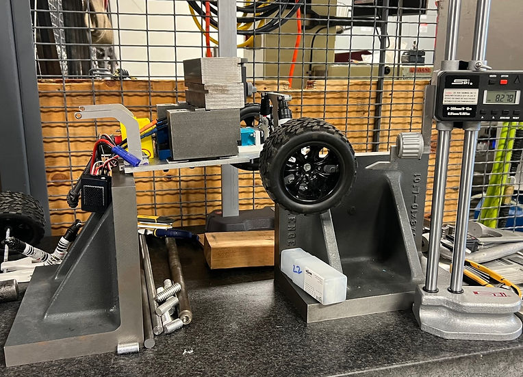
Fig. 4: Deflection Test Setup

Fig. 5: Measuring Method
Figures 4 and 5 show how the Chassis Deflection Test was set up to measure the amount of deflection the chassis experienced when weight was applied to the center of the chassis plate. The initial height from the table was measured using the height gauge indicator and was measured again each time a 6lb mass was added to the chassis.